
Intial wing design parameters
The purpose of this step is to come up with some sort of initial design for the aircraft wing. This would include span, chord and airfoil shape — as well as thickness of the wing. We’re going to be using expanded polystyrene (EPS) foam for the wing material since that’s all I have available. Ideally, I’d find something to laminate it with in order to reduce it’s Reynolds number.
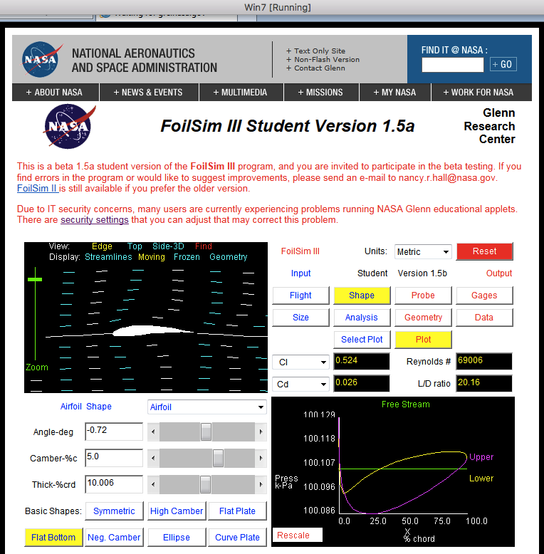
Since I don’t know much about wing design, besides the guidelines we discussed in the last post, I’m going to use the help of a simulator. The specific one I’ll be using is NASA’s FoilSim III — which I found really surprisingly easy to use.
Note: It’s easy to use but it was a nightmare to setup. I had to create a Windows virtual machine (since I’m running a Mac) and install the Java SDK and disable all security settings before I could get the 15 year old Java applet to finally run.
Goal
Before messing around with the FoilSim app, just keep the design parameters in mind:
\[\text{Lift} = \text{Plane Weight} + ~30\%\]The 30% there is a buffer.
Also,
- Low wing loading (\(\lt 50 kg/m^2\))
- High aspect ratio
While we’d normally need some sort of weight measurement, I’m going to consider 1.5kg as a good starting point (for batteries, solar cells and wing body) considering a miniature version of our plane. At the end of this exercise, we’ll consider whether this is a meaningful number or not — but let’s not let that hold us up for now.
Here’s what we expect to get from FoilSim:
- Drag, in Newtons (which is the force that our motor will need to overcome)
- Speed (to tell us what speed we should fly for efficient energy consumption)
- Stall speed (we need to always fly above the stall speed)
- Wing dimensions (span, chord, airfoil shape)
FoilSim time
While messing with FoilSim, I learned a few things that I really should clarify:
- The lift changes with angle of attack (the incline of the wing, relative to the horizontal plane). I considered the \(\text{Lift} = \text{Weight} + 30\%\) guideline above at the neutral angle of attack of \(\alpha = 3 \deg\).
Here’s the result:
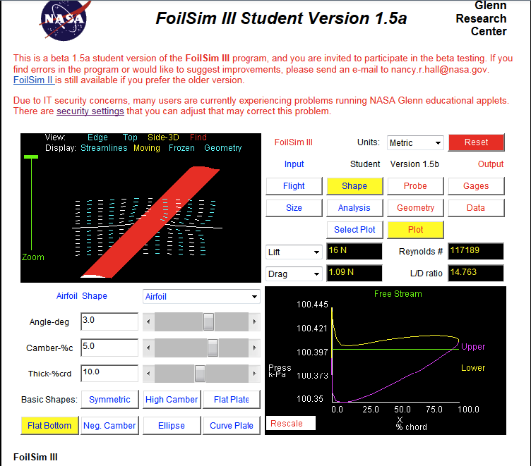
Ended up looking somewhat similar to this glider airfoil, even though I just messed around with alot of knobs until I found the results I was looking for. If I knew how to simulate the simulator, I could write a loop to test ranges of values and programmatically find the most desired result. Anyway, the results are pretty good (though definitely not the best possible).
I had to pick a higher speed of 30 km/h in order to get the necessary lift (16N ≈ 1.6kg). Here’s the raw output data in txt format (View wing data).
Results
 Camber = 5.0 % chord , Thickness = 10.0 % chord ,
 Chord = 0.2 m , Span = 2.0 m , Aspect Ratio = 10 ,
 Surface Area = 0.4 sq m ,
  Angle of attack = 3.0 degrees ,
 Standard Earth Atmosphere
 Altitude = 75 m , Density = 1.216kg/cu m
 Pressure = 100.365kPa, Temperature = 14C,
 Airspeed = 30 km/hr ,
  Lift  = 16 Newtons
  Drag  = 1 Newtons